Yesterday I did my first container-based PostgreSQL version upgrade. In my case the upgrade was from version 13 to 14. In hindsight I was quite naïve. 😅
I was always wondering why distros kept separate data directories for different versions … now I know: you can’t do in-place upgrades with PostgreSQL. You need to have separate data directories as well as both version’s binaries. 😵 Distros have their mechanisms for it, but in the container world you’re kind of on your own.
Well not really … it’s just different. I found there’s a project that specializes in exactly the tooling part of the upgrade. After a little trial an error (see below) it went quite smoothly.
Procedure
In the end it came down to the following steps:
Stop the old postgres container.
Backup the old data directory (yay ZFS snapshots).
Create the new postgres container (with a new data directory; in my case via Ansible)
Stop the new postgres container.
Run the upgrade. (see command below)
Start the new postgres container.
Run vacuumdb as suggested at the end of the upgrade. (see command below)
The Upgrade Command
I used the tianon/postgres-upgrade container for the upgrade. Since my directory layout didn’t follow the “default” structure I had to mount each version’s data directory separately.
I set the POSTGRES_INITDB_ARGS to what I used when creating the new Postgres container’s data directory. This shouldn’t be necessary because we let the new Postgres container initialize the data directory. (see below) I left it in just to be safe. 🤷
I explicitly mounted something to the container’s /var/lib/postgresql directory in order to have access to the upgrade logs which are mentioned in error messages. (see below)
The Vacuumdb Command
Upgrading finishes with a suggestion like:
Upgrade Complete —————- Optimizer statistics are not transferred by pg_upgrade. Once you start the new server, consider running: /usr/lib/postgresql/14/bin/vacuumdb –all –analyze-in-stages
We can run the command in the new Postgres container:
When you’re not using the default directory structure there’re some pitfalls. Mounting the two versions’ data directories separately is easy enough … it says so in the README. It’s what it doesn’t say that makes it more difficult than necessary. 😞
Errors When Initializing the New Data Directory
The first error I encountered was that the new data directory would get initialized with the default initdb options. where I used an optimized cargo-culted incantation which was incompatible (in my case --no-locale --encoding=UTF8). The upgrade failed with the following error:
lc_collate values for database “postgres” do not match: old “C”, new “en_US.utf8”
So I made sure I created the new database container (with the correct initdb args) before the migration fixed this.
Extra Mounts for the Upgrade
What tripped me really up was that when something failed it said to look into a specific log file which I couldn’t find. 🤨 I had to also mount something to the /var/lib/postgres directory which then had all the upgrade log files. 😔
This also solved another of my problems where the upgrade tool wanted to start an instance of the Postgres database, but failed because it couldn’t find a specific socket … which also happens to be located in the directory mentioned above.
Authentication Errors After Upgrade
After the upgrade I had a lot of authentication errors although non of the passwords should have changed.
FATAL: password authentication failed for user “nextcloud”
After digging through the internet and comparing both the old and new data directories it looked like the password hashing method changed. It changed from md5 to scram-sha-256 (in pg_ hda.conf the line saying host all all all scram-sha-256). 😑Just re-setting (i.e. setting the same passwords again) via ALTER ROLE foo SET PASSWORD '...'; on all users fixed the issue.🤐
I tried to find out if you can use Posteo with a custom domain. And the short answer is: no.
Andy Schwartzmeyer found out the long answer. 👏😀 I implemented it for my blog and so far I’m happy. Interestingly enough it’s the receiving side that needs an external service. I currently use Forward Email‘s free tier, because I already have publicly known email addresses that I automatically collect emails from.
I always had the impression that sending mails is made more difficult in order to combat spammers, but what do I know. 🤷 Sending only needs to include Posteo in the SPF rules and adding a sender identity (usable after a one week cool down 🙈).
Backing up encrypted ZFS datasets you’ll see that ZFS breaks up the encryption hierarchy. The backed up datasets will look like they’ve all been encrypted separately. You can still use the (same) original key to unlock all the datasets, but you’ll have to unlock them separately. 😐
This howto should help you bring them back together when you have to restore from a backup.
Assuming we’ve created a new and encrypted pool to restore the previous backup to (I’ll call it new_rpool). We send our data from the backup pool to new_rpool.
Note that we’re using zfs send -w which sends the encrypted blocks “as is” from the backup pool to new_pool. This means that these datasets can only be decrypted with the key they were originally encrypted with.
Also note that you cannot restore an encrypted root/pool dataset with another encrypted one: i.e. we can’t restore the contents/snapshots of rpool to new_rpool (at least not without decrypting them first on the sender, sending them unencrypted and reencrypting them upon receive). Luckily for me that dataset is empty. 😎
Anyway … our new pool should look something like this now:
$ zfs list -o name,encryption,keystatus,keyformat,keylocation,encryptionroot -t filesystem,volume -r new_rpool
NAME                   ENCRYPTION   KEYSTATUS    KEYFORMAT   KEYLOCATION  ENCROOT
new_rpool              aes-256-gcm  available    passphrase  prompt       new_rpool
new_rpool/ROOT         aes-256-gcm  unavailable  raw         prompt       new_rpool/ROOT
new_rpool/ROOT/ubuntu  aes-256-gcm  unavailable  raw         prompt       new_rpool/ROOT/ubuntu
[...]
Note that each dataset is treated as it is encrypted by itself (visible in the encryptionroot property). To restore our ability to unlock all datasets with a single key we’ll have to to some work.
First we have to unlock each of these datasets. We can do this with the zfs load-key command (my data was encrypted using a raw key in a file, hence the -L file:///...):
Although zfs load-key is supposed to have a -r option that works when keylocation=prompt it fails for me with the following error message 🤨:
sudo zfs load-key -r -L file:///tmp/backup.key new_rpool/ROOT

alternate keylocation may only be 'prompt' with -r or -a
usage:
        load-key [-rn] [-L <keylocation>] <-a | filesystem|volume>


For the property list, run: zfs set|get


For the delegated permission list, run: zfs allow|unallow
The keystatus should have changed to available now:
$ zfs list -o name,encryption,keystatus,keyformat,keylocation,encryptionroot -t filesystem,volume -r new_rpool
NAME                   ENCRYPTION   KEYSTATUS    KEYFORMAT   KEYLOCATION  ENCROOT
new_rpool              aes-256-gcm  available    passphrase  prompt       new_rpool
new_rpool/ROOT         aes-256-gcm  available    raw         prompt       new_rpool/ROOT
new_rpool/ROOT/ubuntu  aes-256-gcm  available    raw         prompt       new_rpool/ROOT/ubuntu
[...]
We can now change the encryption keys and hierarchy by inheriting them (similar to regular dataset properties):
When we list our encryption properties now we can see that all the datasets have the same encryptionroot. This means that unlocking it unlocks all the other datasets as well. 🎉
$ zfs list -o name,encryption,keystatus,keyformat,keylocation,encryptionroot -t filesystem,volume -r new_rpool
NAME                   ENCRYPTION   KEYSTATUS    KEYFORMAT   KEYLOCATION  ENCROOT
new_rpool              aes-256-gcm  available    passphrase  prompt       new_rpool
new_rpool/ROOT         aes-256-gcm  available    passphrase  none         new_rpool
new_rpool/ROOT/ubuntu  aes-256-gcm  available    passphrase  none         new_rpool
[...]
Restoring Dataset Properties
This howto doesn’t touch restoring dataset properties, because I’ve not been able to reliably backup dataset properties using the -p and -b options of zfs send. Therefore I make sure that I have a (manual) backup of the dataset properties with something like `zfs get all -s local > zfs_all_local_properties_$(date -Iminutes).txt`
Update 2022-04-04: I’ve updated the article to eliminate NAT on the cloud server side of the VPN. For the router I’ve investigated and triedseveralsolutions.
For a long time I’ve wanted to have a proper IPv6 network at home. Although not always straight forward (because it’s disabled by default or having less capable UI for configuration) I also wanted to be connected to the Internet via IPv6. Although all pieces of my network are IPv6-capable I’m stuck with an ISP that won’t enable it for DSL customers (not even as an “yes, I really want this and I’m willing to deal with the fallout” opt-in). I’ve skimmed NAT64 tutorials for OpenWRT over the years, but most of them were recommending software not updated since 2011. 😨 … and Internet hearsay says: NAT64 is lame! … literally! Implementations seem to prefer IPv4 in the presence of NAT64, because NAT64 is additional complexity on top of IPv4, hence assuming pure IPv4 will be faster).
So a proper IPv6 tunnel it is! It seems all but one 4to6 tunnel brokers have given up … and besides why give someone else your data? I figured a small (~3€/month) server and a little elbow grease would do the job as well. 🤠
The Home Situation
My home network consists of 3 UniFi Access Points, 2 UniFi Switches and a UniFi 3-Port Gateway. As a testament to Ubiquiti’s–at best mediocre–controller UI and basically non-scriptable configuration I’ve always hesitated to embrace it fully. I’ve kept my old–but still supported–OpenWRT router as my DNS server, because in the Unifi world DNS is not configurable beyond a “create DNS entries for DHCP hostnames” switch. Anyway … the Ubiquiti Gateway is connected to the DSL modem, so all IPv4 traffic goes that way.
Conventions
I’ll pretend my current IPv4 network is 10.11.12.0/24 and use the fd00:0011:0012::/48ULA prefix for the IPv6 configuration. You should generate a random global ID and use it in your configuration. This is meant to prevent clashes when different (i.e. separately maintained) networks are merged at some point. The subnet ID (i.e. the 4th segment) still gives us enough leeway to segment our network and still have full /64s for each of them 😎. We’ll use the 13 segment for the home network (named “LAN”). We’ll assume the WireGuard VPN cloud endpoint has an address and prefix of 2000:30:40:50::1/64.
By convention I’ll use .1 or ::1 to signify the UniFi gateway and .2 or ::2 to signify the OpenWRT router in the home network.
Configuration: UniFi Gear
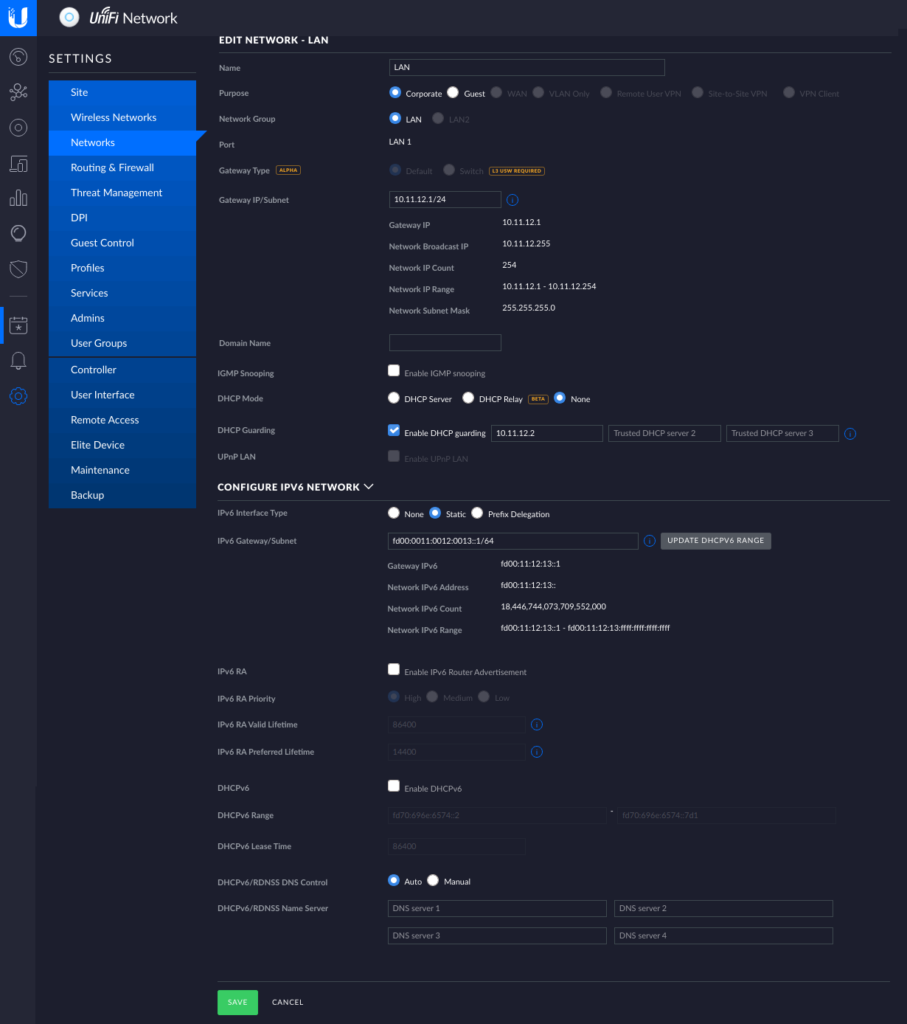
The Ubiquiti gear needs to at least be aware of the networks that are going to be routed through it. This also means that we have to tell it we want to have an IPv6 network also. But in order to have more control over what comes next I made the OpenWRT router the DHCP server of the network.
UnifI Controller: network configuration
Notice that I turned off UniFi’s DHCP server and not activated any of the IPv6 DHCP or RA features here. A word of warning: whatever you put in the Gateway/Subnet fields UniFi will configure it’s gateway to have that IP address! … why would anyone ever use anything else as a gateway. 😒 Also we won’t need port forwarding, because we’ll have the OpenWRT router connect out.
Configuration: Cloud Server
I chose Hetzner Cloud for my VPN endpoint, as their servers have native IPv6 connections and every server gets a /64. Their smallest server costs around ~3€/month. I chose a Ubuntu 20.04 image and configured an SSH key. We then can log in and install WireGuard and something like UFW:
apt update
apt install linux-image-generic-hwe-20.04
apt full-upgrade
apt install wireguard ufw
# make sure we can still connect via SSH
ufw allow 22/tcp
# start firewall
ufw enable
Now we can configure the WireGuard VPN endpoint. Note that we’ll only configure it for IPv6 connectivity!
# generate keys
wg genkey > wg.key
wg pubkey < wg.key > wg.pub
wg genpsk > wg.psk
# TODO: delete these files when configuration is done!
Create a file /etc/wireguard/wg0.conf with the following content:
[Interface]
# Hetzner Cloud VPN endpoint
Address = 2000:30:40:50::3/64
PrivateKey = <contents of wg.key>
ListenPort = 48158

PreUp = echo 1 > /proc/sys/net/ipv6/conf/all/forwarding
# see https://docs.hetzner.com/robot/dedicated-server/ip/additional-ip-adresses/#subnets
# make sure ...:1 routes to the host device
PreUp = ip route add 2000:30:40:50::1/128 dev eth0
# stop routing the whole prefix to the host interface (will clash with the rule below)
PreUp = ip route del 2000:30:40:50::/64 dev eth0
# route allowed IPs (see below) to the WireGuard interface (will be added automatically)
#PreUp = ip route add 2000:30:40:50::/64 dev %i

# forward incoming or outgoing traffic from/to the WireGuard interface (%i) by default
PostUp = ip6tables -A FORWARD -i %i -j ACCEPT
PostUp = ip6tables -A FORWARD -o %i -j ACCEPT
PostUp = ufw allow 48158/udp

# revert firewall rules
PostDown = ip6tables -D FORWARD -o %i -j ACCEPT
PostDown = ip6tables -D FORWARD -i %i -j ACCEPT
# restore routing for host interface
PostDown = ip route add 2000:30:40:50::/64 dev eth0
PostDown = ip route del 2000:30:40:50::1/128 dev eth0

[Peer]
# OpenWRT router
PublicKey = <get this from the "Configuration" section on the WireGuard Status page of the OpenWRT router>
PresharedKey = <contents of wg.psk>
AllowedIPs = 2000:30:40:50::/64
The ListenPort is arbitrary. We’ll use it across all peers in this WireGuard VPN for consistency. The PreUp lines make sure the kernel allows forwarding network packages in general and changes the routing that only a single address (i.e. 2000:30:40:50::1) is routed to the host and the rest of the /64 is routed to the WireGuard interface. The PostUp lines allow packets from our VPN to reach the Internet as well as allowing the WireGuard connection through the firewall. %i will be replaced with the name of the WireGuard interface (wg0 in our case). You should replace eth0 with the name of the network interface of the host that is connected to the Internet.
Now we can start the WireGuard VPN endpoint and make sure it’s started on boot with the following commands. You can comment out the [Peer] section and start it now or wait until we’re done configuring the OpenWRT router also.
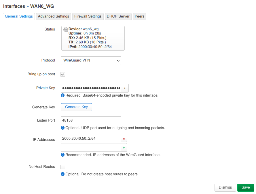
On the “Network > Interfaces” page we add a new interface which I named “wan_wg” using the “WireGuard VPN” protocol. Generate a new private key with the wg genkey command and paste it into the “Private Key” field. Use the same “Listen Port” as for the Cloud VPN endpoint and add 2000:30:40:50::2/64 to the “IP Addresses“.
OpenWRT Router – WireGuard Interface: General Settings
In the “Advanced Settings” tab make sure “Use builtin IPv6-management” is activated.
In the “Firewall Settings” tab assign this interface to the “wan” zone.
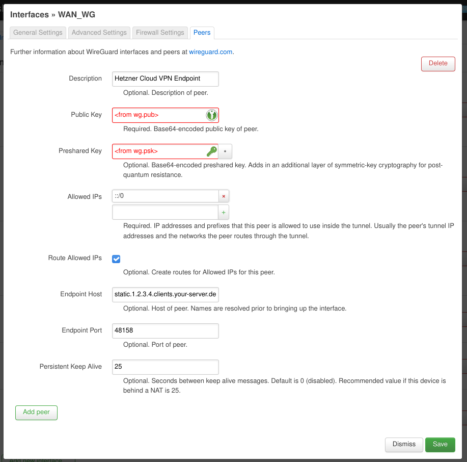
In the “Peers” tab add a new peer and fill in the “Public Key” and “Preshared Key” fields with the contents of the wg.pub and wg.psk files of the Cloud VPN endpoint. The “Allowed IPs” should read ::/0. This may be the single most important configuration. This tells the router that if it doesn’t know where to send a specific IPv6 packet (i.e. because it’s not meant for a device on our home network) it should be sent here. Don’t add anything else otherwise the “Route Allowed IPs” option won’t add a route for ::/0 (ask me how I know 😑)! The “Endpoint Host” should contain a stable public IPv4 address or a hostname to reach the Cloud VPN server. In this case Hetzner Cloud servers are assigned a stable IPv4 address on creation. You can also use a dynamic DNS provider in case you don’t have a stable IP.
OpenWRT Router – WireGuard Interface: Peers
If we have done all the above steps and everything went fine … at this point we should be able to connect from the OpenWRT router out to the Internet via IPv6. We can try this out on the “Network > Diagnostics” page or on the command line.
We can successively test connecting to hosts and interfaces (via ping6 or traceroute6) “further” away:
ping6 2000:30:40:50::2 # the OpenWRT router’s WireGuard address; this side of the tunnel is up
ping6 2000:30:40:50::3 # the Cloud VPN endpoint’s WireGuard address; we can reach the other end of the tunnel
ping6 2000:30:40:50::1 # we can get “out” of the tunnel
ping6 2a00:1450:4001:830::200e # we can connect to the IPv6 Internet (e.g. ipv6.google.com)
ping6 ipv6.google.com # even IPv6 name resolution works
Making our home network IPv6
Now that we can connect out (at least from the OpenWRT router) we still need to make the rest of our home network IPv6 aware. This is the reason I didn’t want the UniFi gear to be the DHCP server in the network any more. With OpenWRT we have much more control over what happens.
To achieve this we have to first tell OpenWRT our “IPv6 ULA-Prefix“. We do this on the “Network > Interfaces” page on the “Global network options” tab. As described above we use fd00:11:12::/48 here. Make sure the first 3 segments are the same on all the IPv6 addresses you configure with this tutorial!
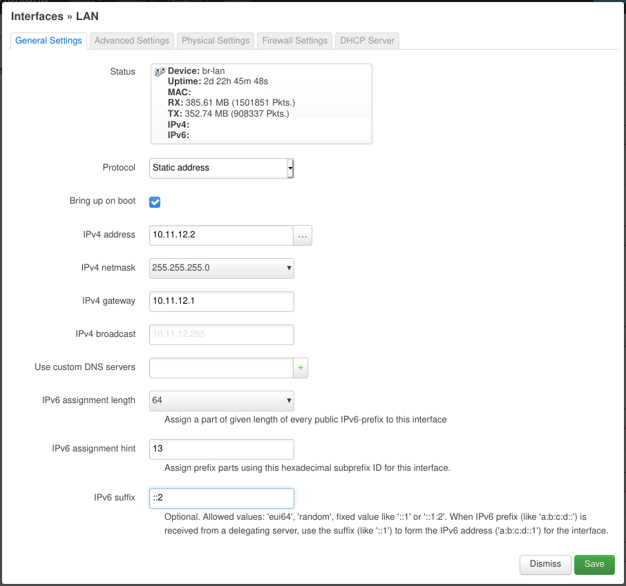
After this we go back to the “Interfaces” tab and edit the “LAN” network. On the “General Settings” tab we set the “Protocol” to “Static address“, the “IPv6 assignment length” to 64, the “IPv6 assignment hint” to 13 (this will become the 4 segment in our IPv6 addresses) and “IPv6 suffix” to ::2.
OpenWRT – LAN Interface: General Settings
On the “Advanced Settings” tab we make sure to have “Use builtin IPv6-management” enabled.
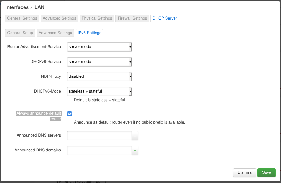
Now we go to the “DHCP Server” tab. On its “General Setup” tab we make sure “Ignore interface” is disabled. On the “IPv6 Settings” tab set “Router Advertisement-Service” and “DHCPv6-Service” to “server mode“, “NDP-Proxy” to “disabled” and “DHCPv6-Mode” to “stateless + stateful“. The most important setting is enabling “Always announce default router“. This makes sure that the OpenWRT router announces to the home network that it is the default router (for IPv6). This is necessary because we use local addresses (i.e. starting with fd...) instead of handing down the public prefix our Cloud VPN endpoint was assigned. (Update: we can delegate the VPN’s public prefix, but since we only have a /64 prefix it will be assigned to only one of our networks basically at random. All others won’t be able to use it. I had the wrong impression that I could use any prefix and segment it for my networks, but it seems /64 prefix is the maximum possible when you want to use common/standard tools. The only “non-standard” way I currently know is Docker which is able to utilize prefixes as long as /80 for its networks and containers.)
OpenWRT – LAN Interface: DHCP IPv6 Settings
This should do the trick. Now other devices on the network should be getting IPv6 addresses from the fd00:11:12:13::/64 address range (check e.g. with ip -6 a). You may need to disconnect and then connect to the network again for the changes to be picked up.
Now you can do the same pinging/tracerouting procedure we did on the OpenWRT router.
Some NAT
During my testing I was not able to ping the Cloud VPN endpoint’s WireGuard interface from my laptop. No amount of config jiggling on the OpenWRT router was helping getting the packages further than its WireGuard interface (i.e. 2000:30:40:50::2). Although I thought we could get by without using NAT 😓.
I’m mostly unhappy about the NAT. I’d like to get rid of it completely hopefully when I find a good way to buy/configure/hand down a larger public prefix assigned to the Cloud VPN endpoint. I’m still figuring out how to properly propagate through WireGuard and the home network (preferably) using the built-in prefix delegation mechanism. Help or ideas would be appreciated on this topic. 😅
My second point of grief is that all external traffic is routed through the <public prefix>::2 address although we have a whole /64 subnet. Somehow routing through the WireGuard network maps all address to ::2 negating the benefit of the masq6_privacy option on the “wan” firewall interface. 😞
Update 2022-02-21: NieX0 in a comment below has instructions for using prefix translation instead of masquerading which I consider a step into the right direction. 😀
Here are some tips to troubleshoot issues with this setup.
EUI64 addresses
You should put the last two segments of the LAN interface’s MAC address (looking like aa:bb:cc:dd:ee:ff) to memory as IPv6 devices use addresses derived from the MAC address (e.g something like fd00:11:12:13:a8bb:ccff:fedd:eeff or fe80::a8bb:ccff:fedd:eeff). Even if we’ve assigned specific addresses to specific devices or interfaces these addresses will still come up in routing or debugging output. There’re tools that help with converting MAC address + IPv6 network prefix into the final IPv6 addresses.
Checking IPv6 addresses
We can use ip -6 a to check what IPv6 address are assigned to interfaces on specific devices. Beware these can be quite a few. Check if the network prefixes (i.e. the first 4 segments of the IPv6 address) match what we have configured for our networks (and also the fe80:... addresses). Then we look at the host part (i.e. the last 4 segments of the IPv6 address) for the ones we’ve assigned manually or for the EUI64 addresses mentioned above. These will help us identify if our devices got any the IPv6 configuration right.
Checking IPv6 routes
We can use ip -6 r to check if our devices have the right routes configured. The most important one to look out for is the one starting with default via ... . It should point to one if the addresses of the OpenWRT router. We can also use traceroute6 to see what devices the packages go through.
Click on the three dots in the top right corner, select “Export Logins…” and save your passwords info a CSV file (e.g. exported_firefox_logins.csv).
There’s one complication: Firefox will save dates as Unix timestamps (with millisecond resolution) which KeePassXC doesn’t understand, so we’ll have to help it out.
Save the following script into a file (e.g. firefox_csv_date_fix.py).
#!/usr/bin/env python3
#
# Author: Riyad Preukschas <riyad@informatik.uni-bremen.de>
# License: Mozilla Public License 2.0
# SPDX-License-Identifier: MPL-2.0


import csv
import sys

from datetime import datetime


def main():
    if len(sys.argv) != 2:
        print("Usage: {} <exported_firefox_logins.csv>".format(sys.argv[0]), file=sys.stderr)
        exit(1)

    csv_file_name = sys.argv[1]

    with open(csv_file_name, 'rt') as f:
        # field names will be determined from first row
        csv_reader = csv.DictReader(f)
        # read all rows in one go
        rows = list(csv_reader)

    # add new columns with Iso-formatted dates
    for row in rows:
        row['timeCreatedIso'] = datetime.fromtimestamp(int(row['timeCreated'])/1000).isoformat()
        row['timeLastUsedIso'] = datetime.fromtimestamp(int(row['timeLastUsed'])/1000).isoformat()
        row['timePasswordChangedIso'] = datetime.fromtimestamp(int(row['timePasswordChanged'])/1000).isoformat()

    # write out the updated rows
    csv_writer = csv.DictWriter(sys.stdout, fieldnames=rows[0].keys())
    csv_writer.writeheader()
    csv_writer.writerows(rows)


if __name__ == '__main__':
    main()
Call it giving it the path of the exported_firefox_logins.csv file and redirect the output into a new file:
It will add new columns (named: old column name + “Iso”) with the dates converted to the ISO 8601 format KeePassXC wants.
We can now use the fixed_firefox_logins.csv file to import the logins into KeePassXC.
Select Database -> Import -> CSV File... from the menu.
It will ask you to create a new database. Just do it you can get the data into your default database later (e.g. call it firefox_logins.kdbx for now).
In the import form select “First line has field names” and match up KeePassXC’s fields with the columns from the CSV:
KeePassXC Field
Firefox CSV Column
Notes
Group
Not Present
Title
url
Firefox doesn’t have a title field so we use the URL for it.
Username
username
Password
password
URL
url
Notes
httpRealm
I’m not sure how KeePassXC deals with HTTP authentication. There’s no special field for it, so I decided to keep it in the Notes field.
TOTP
Not Present
Icon
Not Present
Last Modified
timePasswordChangedIso
the “Iso” part is important!
Created
timeCreatedIso
the “Iso” part is important!
Have a look at the preview at the bottom. Does the data look sane? 🤨
Sadly KeePassXC doesn’t let us import Firefox’s timeLastUsedIso field into its Accessed field. 😑
All your imported Logins will be inside the “Root” group. I’d suggest creating a new group (e.g. “Firefox Import”) and moving all imported Logins into it.
You can now open your default database and use the Database -> Merge From Database ... menu item, select the firefox_logins.kdbx file to include it’s contents into the current database. You’ll see a new “Firefox Imports” group show up.
You can now move the single entries into the appropriate groups if you want (e.g. “KeePassXC-Browser Passwords” if you use the browser extension).
When I started playing with LXD I just accepted the default storage configuration which creates an image file and uses that to initialize a ZFS pool. Since I’m using ZFS as my main file system this seemed silly as LXD can use an existing dataset as a source for a storage pool. So I wanted to migrate my existing containers to the new storage pool.
Although others seemed to to have the same problem there was no ready answer. Digging through the documentation I finally found out that the lxc move command had a -s option … I had an idea. ? Here’s what I came up with …
Preparation
First we create the dataset on the existing ZFS pool and add it to LXC.
pool1 is the old pool backed by the image file and is used by some containers at the moment as can be seen in the “Used By” column. pool2 is added by not used by any contaiers yet.
Moving
We now try to move our containers to pool2.
# move container to pool2
lxc move some_container some_container-moved -s=pool2
# rename container back for sanity ;)
lxc move some_container-moved some_container
We can check with lxc storage list whether we succeeded.
If you’re an Ansible user and encounter the following error:
unix_listener: "..." too long for Unix domain socket
you need to set the control_path option in your ansible.cfg file to tell SSH to use shorter path names for the control socket. You should have a look at the ssh_config(5) man page (under
In the company I work for we’re using RabbitMQ to offload non-timecritical processing of tasks. To be able to recover in case RabbitMQ goes down our queues are durable and all our messages are marked as persistent. We generally have a very low number of messages in flight at any moment in time. There’s just one queue with a decent amount of them: the “failed messages” dump.
The Problem
It so happens that after a botched update to the most recent version of RabbitMQ (3.5.3 at the time) our admins had to nuke the server and install it from scratch. They had made a backup of RabbitMQ’s Mnesia database and I was tasked to recover the messages from it.
This is the story of how I did it.
Since our RabbitMQ was configured to persist all the messages this should be generally possible. Surely I wouldn’t be the first one to attempt this. ?
Looking through the Internet it seems there’s no way of ex/importing a node’s configuration if it’s not running. I couldn’t find any documentation on how to import a Mnesia backup into a new node or extract data from it into a usable form. ?
The Idea
My idea was to setup a virtual machine (running DebianWheezy) with RabbitMQ and then to somehow make it read/recover and run the broken server’s database.
In the following you’ll see the following placeholders:
My first try was to just copy the broken node’s Mnesia files to the VM’s $RABBITMQ_MNESIA_DIR failed. The files contained node names that RabbitMQ tried to reach but were unreachable from the VM.
Error description:
   {could_not_start,rabbit,
       {{failed_to_cluster_with,
            ['$BROKEN_NODENAME'],
            "Mnesia could not connect to any nodes."},
        {rabbit,start,[normal,[]]}}}
So I tried to be a little bit more picky on what I copied.
First I had to reset $RABBITMQ_MNESIA_DIR by deleting it and have RabbitMQ recreate it. (I needed to do this way too many times ?)
sudo service rabbitmq-server stop
rm -r $RABBITMQ_MNESIA_DIR
sudo service rabbitmq-server start
Stopping RabbitMQ I tried to feed it the broken server’s data in piecemeal fashion. This time I only copied the
rabbit_*.[DCD,DCL]
and restarted RabbitMQ.
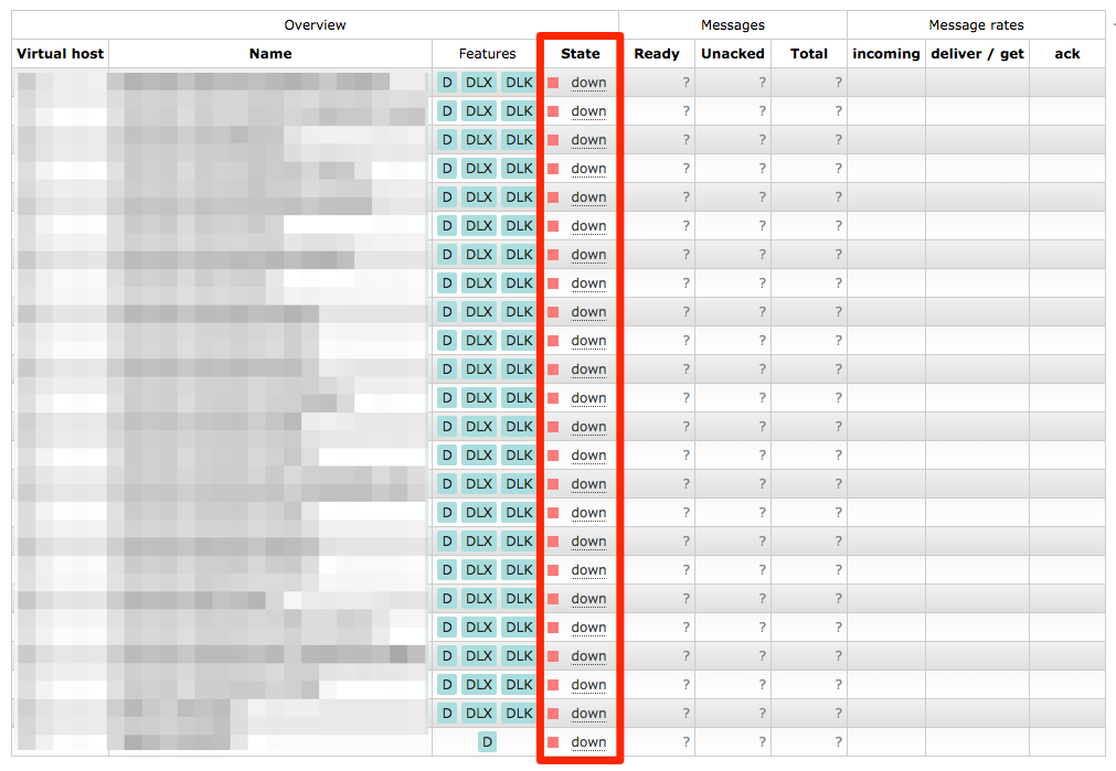
RabbitMQ’s management interface lists all the queues, but it thinks the node they’re on is “down”
Looking at the web management interface there were all the queues we were missing, but they were “down” and clicking on them told you
The object you clicked on was not found; it may have been deleted on the server.
Copying any more data didn’t solve the issue. So this was a dead end. ?
2nd Try
So I thought why doesn’t the RabbitMQ in the VM pretend to be the exact same node as on the broken server?
So I created a
/etc/rabbitmq/rabbitmq-env.conf
with
NODENAME=$BROKEN_NODENAME
in there.
I copied the backup to $RABBITMQ_MNESIA_DIR (now with the new node name) and fixed the permissions.
Now starting RabbitMQ failed with
ERROR: epmd error for host $BROKEN_HOST: nxdomain (non-existing domain)
I edited
/etc/hosts
to add $BROKEN_HOST to the list of names that resolve to 127.0.0.1.
Now restarting RabbitMQ failed with yet another error:
Now what? Why don’t I try to give it the Mnesia files piece by piece again?
Reset $RABBITMQ_MNESIA_DIR
Stop RabbitMQ
Copy
rabbit_*
files in again and fix their permissions
Start RabbitMQ
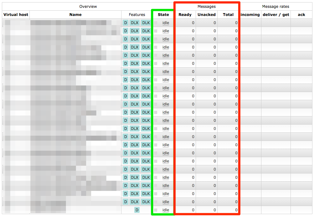
All our queues were back and all their configuration seemed OK as well. But we still didn’t have our messages back yet.
The queues have been restored, but they have no messages in them
Solution
So I tried to copy more and more files over from the backup repeating the above steps. I finally reached my goal after copying
rabbit_*
,
msg_store_*
,
queues
and
recovery.dets
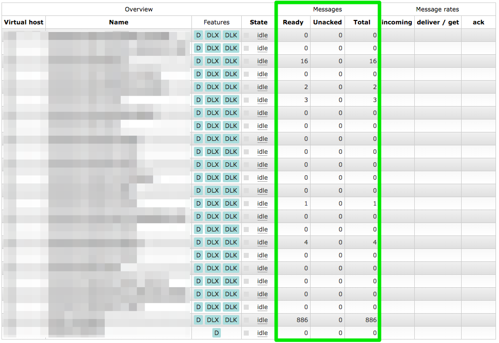
. Fixing their permissions and starting RabbitMQ it had all the queues restored with all the messages in them. ?
Queues and messages restored
Now I could use ordinary methods to extract all the messages. Dumping all the messages and examining them they looked OK. Publishing the recovered messages to the new server I was pretty euphoric. ?